Documentation
Board Revision: 3.1.x (Latest)
(boards shipped in 2024 & 2025)
Contents
Getting Started
So you've got your Sonatino — now what? Let's make some sound!
The easiest way to get up and running with Sonatino is to install the Arduino IDE and flash an example sketch to the board. To do that, follow the steps below:
- Download and install the Arduino IDE (version 2.0 or above).
- Install Arduino-ESP32 by referring to these instructions. Essentially, you need to add the following to "Additional boards manager URLs" (in Preferences):https://raw.githubusercontent.com/espressif/arduino-esp32/gh-pages/package_esp32_index.jsonAfter adding the URL, open the Boards Manager, search for "esp32", and install "esp32 by Espressif Systems".
Note: For compatibility with other libraries (including ESP8266Audio), it's recommend that you use version 2.x.x of the esp32 board package. Version 3 of the esp32 package is gaining support, but as of now, some libraries may not work with it as expected. - Install the ESP8266Audio library in the Arduino IDE (using the Library Manager or manually from here). This library is required for the example sketch to work.
- Download the Sonatino Examples and open playback/playback.ino with the Arduino IDE.
- Make sure both level selection DIP switches on the board are set to the "ON" position (positioned to the right when the board is oriented as shown in the images in this documentation). They should be set to "ON" by default, but can be changed using a small toothpick or paperclip.
- Plug Sonatino into your computer using a USB-C cable. If a green LED does not light up on the board, try a different USB port or cable.
- Within the Arduino IDE, select the port corresponding to the Sonatino board (will vary based on your system), and make sure the board is set to "ESP32S3 Dev Module". For the serial monitor to work, you'll also need to set "USB CDC on Boot" to "Enabled".
- Click the "Upload" button to compile the sketch and flash it to Sonatino.
Congratulations! If everything went well, you should see the RGB LED begin to flash on the board, and if you plug in a pair of headphones you should hear music playing. Go ahead and try any of the other example sketches or start writing your own code to do something amazing!
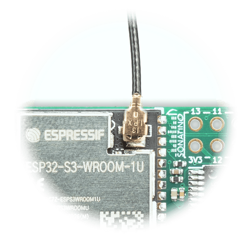
Antenna Note: The "audio-playback-example" sketch does not use any wireless features, so the antenna can be left disconnected. If you want to use WiFi or BLE in another sketch, don't forget to carefully connect the external antenna to the U.FL connector on the board. Follow these tips for properly connecting and disconnecting the antenna.
Board Overview
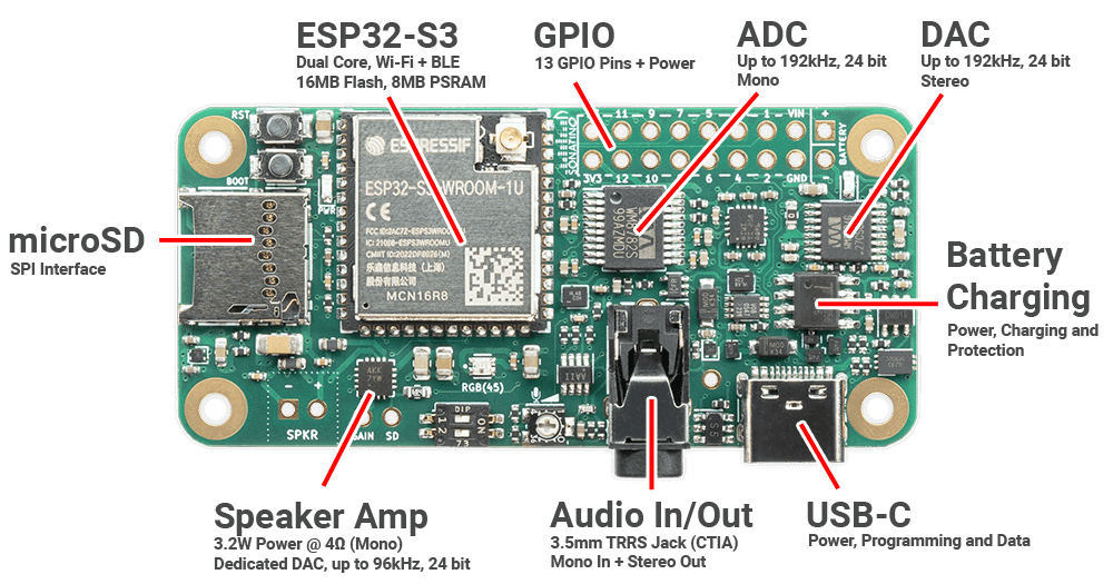
MAIN COMPONENTS
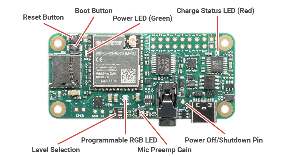
CONTROLS & INDICATORS
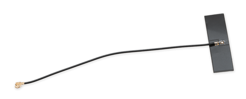
ANTENNA
ANTENNA CONNECTION
OPTIONAL COMPONENTS
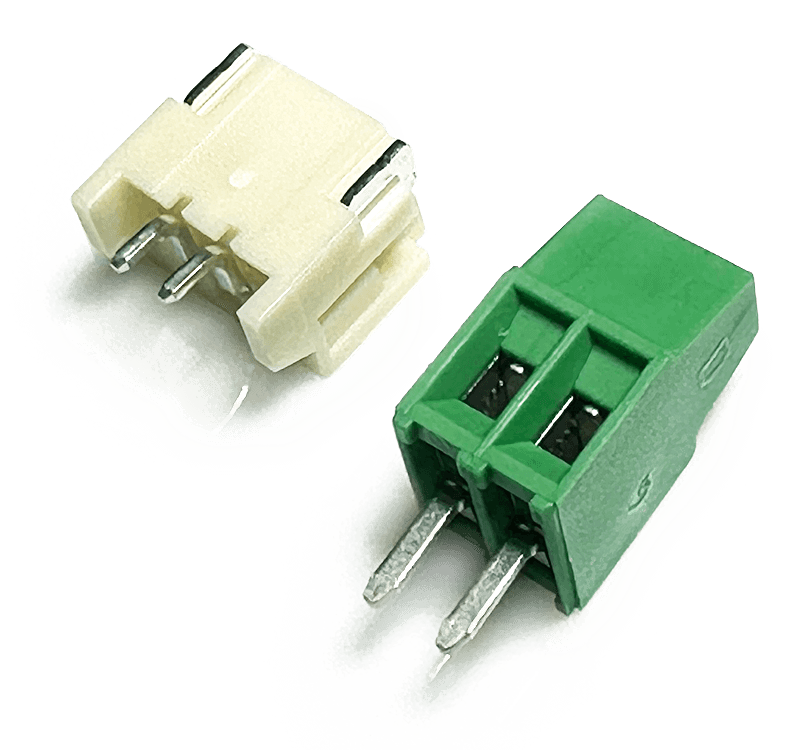
- The JST PH 2 connector (left) can soldered to the bottom of the board for battery connections.
- The terminal block (right) can be soldered to the SPKR pins for speaker wire connections.
- (not included) 2.54mm headers can be soldered to the GPIO + power pins for easy prototyping.
| Component | Function |
|---|---|
ESP32-S3 | Microcontroller with WiFi and BLE |
GPIO | General Purpose Input/Output |
ADC | Analog-to-Digital Converter (audio input) |
DAC | Digital-to-Analog Converter (audio output) |
Battery Charging | Supports 3.7V LiPo/Li-Ion batteries |
USB-C | Interface for power and programming |
Audio In/Out Jack | Accepts a 3.5mm TRRS cable (mono in, stereo out) |
Speaker Amp | Can drive a small 4Ω speaker connected to SPKR pins (or optional terminal block) |
microSD Card Slot | Read/write access to microSD card using SPI interface |
Reset Button | Resets the ESP32-S3 microcontroller |
Boot Button | Forces the ESP32-S3 into flashing mode |
Power LED | Green LED indicates the board has power |
RGB LED | Programmable RGB Status LED |
Charge Status LED | Red LED indicates battery charging status |
Mic Preamp Gain | Clockwise rotation increases mic gain |
Level Selection | Switch #1: Input Level (OFF=Line, ON=Mic) |
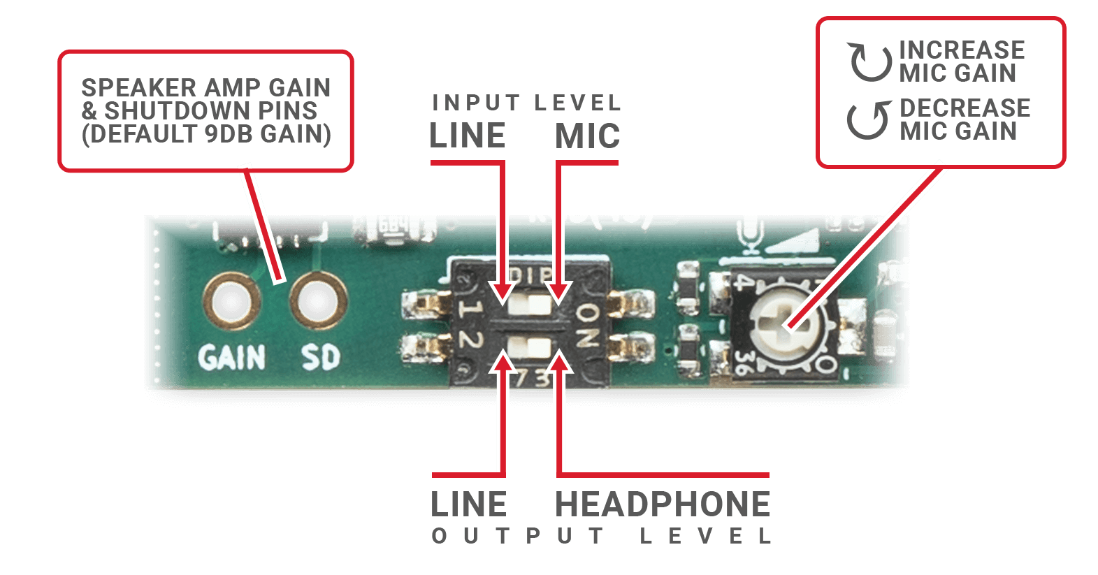
- Use a small toothpick or paperclip to carefully adjust the level selection DIP switches as needed.
- The mic gain control is adjustable with a small phillips or flat head screwdriver. Do not turn with excessive force; the trimpot is fragile and only has 250° of rotation from minimum to maximum.
- For adjusting gain of the speaker amp or to select a different channel mode (default is left/2 + right/2), refer to the MAX98357A datasheet. See pinout for details.
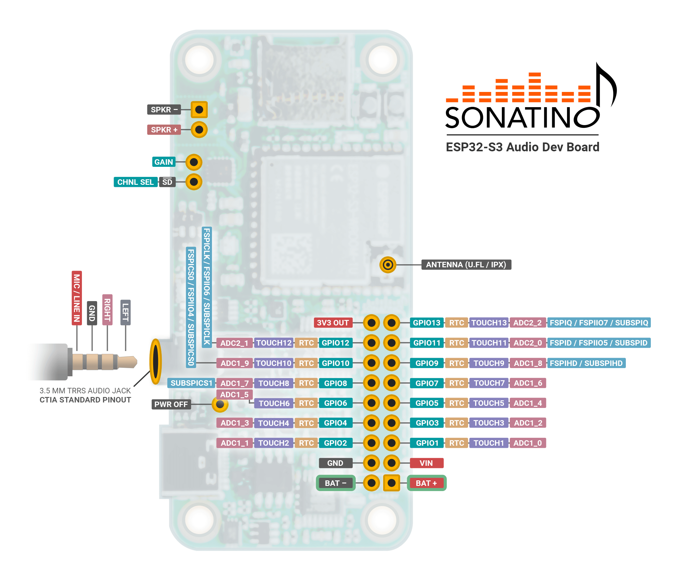
Pinout
| Pin | Component | Function |
|---|---|---|
VIN | Power | Power Input Positive (+) 5V (note) |
3V3 | Power | 3.3V Output (Regulated) (note) |
Battery- | Power | Battery Negative (-) |
Battery+ | Power | Battery Positive (+) 5V Max |
GND | Power | Ground |
PWR OFF | Power | Power Off (Active LOW) (note) |
GPIO 0 | Boot / MCLK | Boot / MCLK |
GPIO 1-13 | GPIO | General Purpose I/O |
GPIO 14 | DAC | Mute (Active LOW) (audio jack only) |
GPIO 15 | DAC | BCLK / SCK |
GPIO 16 | DAC | LRCLK / WS |
GPIO 17 | DAC | Data (Out) |
GPIO 18 | ADC | Sample Rate (note) |
GPIO 21 | ADC | Bit Depth (note) |
GPIO 38 | ADC | BCLK / SCK |
GPIO 39 | ADC | LRCLK / WS |
GPIO 40 | ADC | Data (In) |
GPIO 41 | microSD (SPI) | D3 / CS / SS |
GPIO 42 | microSD (SPI) | CLK / SCK |
GPIO 43 | microSD (SPI) | CMD / SI / MOSI |
GPIO 44 | microSD (SPI) | D0 / SO / MISO |
GPIO 45 | RGB LED | Programmable RGB LED (WS2812B) |
GPIO 46 | Headphone Amp | Gain 1 (note) |
GPIO 47 | Headphone Amp | Gain 0 (note) |
GPIO 48 | All Amps | Amp Shutdown (Active LOW) |
GAIN | Speaker Amp | Gain (note) |
SD / CHNL_SEL | Speaker Amp | Shutdown and Channel Selection (note) |
SPKR + | Speaker Amp | Speaker Positive (+) |
SPKR - | Speaker Amp | Speaker Negative (-) |
AUDIO JACK | 3.5mm TRRS (CTIA) | Tip: Left Out |
ANTENNA | Antenna Connector | WiFi/Bluetooth Antenna (U.FL/IPX) |
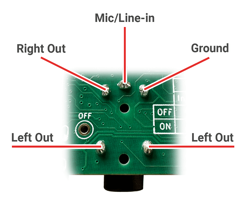
AUDIO JACK PINS
Technical Details
Power
- Do not attempt to power the board using the 3V3 output pin. This pin is intended for powering 3.3V peripherals (generally around 400mA max) using Sonatino's onboard regulator. Connecting a power source to this pin may damage the board.
- The board can be powered from USB-C, DC power (VIN), or a 3.7V lithium battery. If USB-C and VIN are both connected (with VIN at 5V), the board will draw power from VIN. If a battery is also connected, USB-C or VIN will charge the battery while powering the board.
- VIN should normally be 5V. Due to some voltage drop in the board's power protection circuitry and tolerance of the regulators, you can supply 3.6V up to 6V, but please be careful not to exceed 6V as it is likely to damage to the board.
- Sonatino can draw significant current at times (depending on usage; can be 1A or more). If your power source cannot supply enough current, you may experience unexpected behavior.
Battery
- The charging circuit is configured to deliver up to 500mA of current to a rechargeable lithium battery. Please check that your battery can handle this charging rate, especially for batteries with less than 500mAh of capacity.
- When connecting a battery for the first time, you may need to briefly short the negative (-) battery pin to ground (GND) to enable operation. This is a known behavior of the battery protection chip. The battery charge status LED may also remain illuminated when no battery is connected; this is normal and does not indicate a problem with the board.
- Battery voltage can be monitored using GPIO 10. To enable this feature, solder the jumper pad labeled "JP2" on the bottom of the board (after doing that, GPIO 10 can only be used for battery monitoring). With JP2 bridged, GPIO 10 is connected to the battery through a voltage divider (a 150kΩ resistor to the battery and a 470kΩ resistor to ground). Using 12-bit ADC values from GPIO 10 (values 0-4095), battery voltage can be estimated using this formula:
Vbat = ADC_READING ÷ 941
For best accuracy, use the average from multiple readings. - The PWR OFF pin (near the USB-C connector) can be used to shut down the board while still allowing the battery to charge. To shut down the board, connect the PWR OFF pin to ground (GND) using a jumper wire or a switch.
- A few ways to reduce power consumption and extend battery life:
- Turn off wireless functions on the ESP32-S3 when not in use.
- Configure the ESP32-S3 to use a lower CPU frequency or dynamic frequency scaling (DFS).
- Set GPIO 48 to LOW: this shuts down the speaker amp, headphone amp, and microphone preamp.
- Set GPIO 14 to LOW to mute the DAC.
- Stop outputting a MCLK signal on the ESP32-S3's GPIO 0 (may require calling i2s_stop()). This will power down the ADC and DAC.
- Put the ESP32-S3 into light sleep or deep sleep (esp_light_sleep_start() or esp_deep_sleep_start()). If you've shut down the amps by setting GPIO 48 to LOW, don't forget to call gpio_hold_en(GPIO_NUM_48) and gpio_deep_sleep_hold_en() before sleeping to keep the pin held low.
- Remove any microSD card if you aren't using it.
- You can disable the green power LED by carefully cutting the trace between the two jumper pads of JP1 on the underside of the board.
Programming
- Sonatino can be programmed using a number of different software tools. While Arduino IDE is probably the easiest for getting started, PlatformIO and ESP-IDF offer some additional benefits for more advanced projects.
- When uploading code, Arduino IDE will usually take care of putting the board into flashing mode and then resetting the board when the upload is complete. If that doesn't work, check that the correct port and board is selected, then try again. Some development tools don't handle the flashing process correctly by default, so you may need to adjust your software's board settings.
- In rare cases, you may need to manually put the board into flashing mode. This can be done by holding down the boot button while pressing the reset button, then releasing both buttons.
Audio
- Some audio libraries disable the master clock (MCLK, also called MCK, mck_io_num, or main_clock) by default. Sonatino requires this to be enabled and set to GPIO 0 for the DAC and ADC to work. If you aren't hearing any output, please double-check that you've configured GPIO 0 as the master clock.
- Sonatino uses separate bit clock (BCLK) and word clock (LRCLK) lines for the DAC and ADC — as noted in the pinout. The ESP32-S3 supports two I2S ports, so you can configure and use the DAC and ADC simultaneously (technically they could share those lines, but Sonatino wires them separately for added flexibility).
- The 3.2W speaker amp has its own independent DAC and shares the same I2S lines as the main DAC. The speaker amp's DAC can operate up to 96kHz, so only the main DAC (via the 3.5mm jack) will work for higher sample rates (up to 192kHz).
- GPIO 18 and GPIO 21 are connected to FSAMPEN and IWL pins of the WM8782 (ADC), respectively. These pins are used to configure the ADC's sample rate and word length. See the WM8782 datasheet for more information.
- GPIO 46 and GPIO 47 are connected to GAIN1 and GAIN0 of the TPA6132A2 (Headphone Amp), respectively. The default state corresponds to 0 dB gain (GAIN0 is pulled HIGH and GAIN1 is pulled LOW), but can be set to -6 dB, 0dB, 3dB, or 6 dB based on pin state. See section 7.4.1 of the TPA6132A2 datasheet for more information.
- The SD pin (next to the speaker output) is connected with a 680kΩ resistor to GPIO 48 (amp shutdown), which in turn is normally pulled HIGH (to 3.3V) by a 10kΩ resistor. By default, this means the speaker amp is enabled and in left/2 + right/2 mode (it outputs an average of both stereo channels). When GPIO 48 is set to LOW (in software), this amp — along with the other amps — will be shut down. If you wish to ouput only the right channel, pull up the SD pin to 3.3V through a 330kΩ resistor. For the left channel only, connect it directly to 3.3V.
- The GAIN pin (next to the speaker output) is normally unconnected, corresponding to 9 dB of gain. Different levels of speaker gain can be selected by connecting the GAIN pin as described in the MAX98357A datasheet.
- Without properly setting volume/gain (in software and hardware), audio output from Sonatino can be very loud! It can also become distorted if the volume is set too high. Please protect your ears and be careful when testing audio output!
- Noise in the audio can be caused by a number of factors including noisy power supplies, antennas that are too close, interference from other devices, and ground loops. If you encounter noise, try to isolate the source of the problem by testing different configurations and settings. USB-C power from a computer can often introduce noise, so try using a different power source if you suspect this is the issue. If noise is only present during wireless communication, try moving the antenna, using a different antenna (or adding shielding between the antenna and board), or lowering the transmit power (esp_wifi_set_max_tx_power() or esp_ble_tx_power_set()).
- Crackling, stuttering, or choppy audio is most often caused by misconfigured settings (sample rate, word length, master clock, DMA buffer, etc.) or by delays in the audio processing pipeline. Double-check that all your settings are correct and that no time-consuming tasks are blocking the delivery of audio samples. You may need to use RTOS programming to take advantage of both cores of the ESP32-S3.
Cases / Enclosures
- Sonatino will fit into some cases designed for the Raspberry Pi Zero, but not all. Cases that are open around the edges of the board generally work without modification, but those with cutouts for ports on the Raspberry Pi Zero (including the official case sold by Raspberry Pi) won't match the ports on Sonatino. Those cases can sometimes be modified by expanding or cutting out new holes for Sonatino's ports.
Datasheets
Microcontroller
DAC
ADC
Stereo Headphone Amplifier
3.2W Amplifier
Microphone Preamplifier
Battery Charger
RGB LED
Additional Resources
Inter-IC Sound (I2S) — Espressif API reference for I2S audio on ESP32-S3
ESP-ADF — Espressif Audio Development Framework
ESP-Skainet — Voice assistant / speech recognition for ESP32-S3
ESP8266Audio — Arduino library for playing audio on ESP8266 and ESP32
pschatzmann/arduino-audio-tools — Arduino Audio Tools
esp32_basic_synth — ESP32 based simple synthesizer project
